Would you like to react to this message? Create an account in a few clicks or log in to continue.

Presents a community forum for all Honda and non Honda fanatics...


    Making Turbo Manifolds Part 1 & 2

    corsa-wp
    corsa-wp


    Number of posts : 38
    Rider Points : 64
    Street Rep : 0
    Registration date : 2009-03-23
    Age : 38
    Location : Kuilsriver

    Making Turbo Manifolds Part 1 & 2 Empty Making Turbo Manifolds Part 1 & 2

    Post  corsa-wp Fri Jun 12, 2009 3:38 pm

    Making Turbo Manifolds Part 1 & 2 2604

    Making Turbo Manifolds, Part 1
    Getting the exhaust gas flow to the turbine
    by Julian Edgar


    At a glance...

    * Heavy gauge bends
    * Manifold flanges
    * Planning
    * Construction hints


    If you fit a turbo to a naturally aspirated engine, or decide to upgrade a turbo to the extent that it no longer fits the standard manifold, you’ll need to make a new manifold. But if you’re on a budget, how do you go about achieving that? Workshops charge an arm and a leg for custom manifolds, but if you can use a few power tools and can access the services of a welder, it’s not hard to do it yourself.
    Making Turbo Manifolds Part 1 & 2 2604_5lo

    Materials Overview

    Two different approaches can be taken to the fabrication of a bespoke exhaust manifold. The most common approach is to make the manifold from heavy gauge, mild steel “steam” pipe. Alternatively, thin stainless steel bends can be used. The heavy gauge pipe is more durable and in many ways is easier to ‘work’ – eg it can be held securely in a vice.

    In addition to the pipe, flanges will also be needed at the head and the manifold. These flanges must be thick so that they do not distort under heat and pressure, so allowing leaks. A flange that is 10mm thick after it has been faced is appropriate for most applications. (More on facing in a moment.) To allow for this machining, it’s good to start with 12mm plate.

    The Bends

    Making Turbo Manifolds Part 1 & 2 2604_8lo

    While known to everyone into modified cars as “steam pipe”, the sorts of bends used to make manifolds are not actually called that at places where you can buy them! Instead, they’re called “buttweld fittings” and as the name suggests, are designed to be welded together. The buttweld fittings of most interest to manifold constructors are the bends. Most commonly used are 45 and 90-degree bends, which are available in short- and long-radius forms. Most manifolds are made from long radius bends which as their name suggests, are less sharp.

    Buttweld bends are available in a variety of sizes. Typically, the quoted size is for the inner diameter (ID). For example, buttweld bends can be bought in 13.9, 18.9, 24.2, 32.4, 38.1 and 49.3mm inside diameters. The wall thickness depends on whether the pipe is standard weight or extra strong; in each case the wall thickness also depends on the diameter of the pipe. For example, in 32mm fittings (ie 1¼ inch), extra strong wall thickness is 4.85mm and standard weight wall thickness is 3.56mm.

    The diameter of the bends is normally matched to the diameter of the ports (or with non-round ports, the cross-sectional area). However, if the ports are very large, a smaller diameter fitting may be used with a transitional cone either incorporated into the first section of pipe or formed within the manifold flange thickness.

    Buttweld fittings are available at engineering supply houses.

    Making Turbo Manifolds Part 1 & 2 2604_4lo

    The Flanges

    Making Turbo Manifolds Part 1 & 2 2604_10lo

    Normal mild steel is able to be used to make the mounting flanges for the manifold and the turbo. In most cases, flat bar can be bought – it’s readily available in a 100 x 12mm size that is suitable for most turbo manifold construction. If bar is not available, flat plate can be used instead.

    Construction

    Buttweld bends are able to be cut with a hacksaw. This is made easier because of their strength – they can be tightly clamped in a vice without unduly distorting. By using a combination of 45 and 90-degree bends, and cutting and shaping their ends, it’s possible to create all sorts of patterns of pipe direction. Buttweld fittings come with a chamfer ground on their ends, allowing good penetration of the weld bead. When the bends are cut off short or are otherwise modified, the chamfer should be re-ground.

    Making Turbo Manifolds Part 1 & 2 2604_7lo

    It’s important that you have a good selection of bends available. Even though it may appear on paper that (say) four 90-degree and two 45-dgree bends are all that will be needed, it’s is wise to buy twice as many bends and so have a variety of options available. The bends shown here cost about AUD$8 each from Blackwoods.

    The manifold and turbo mounting flanges can be cut from the flat bar in a number of ways. These include laser cutting, water jet cutting and oxy-acetylene cutting. For a one-off job, oxy cutting is the simplest: it’s gives the poorest edge (it must be cleaned-up with an angle grinder and/or filing) but any workshop or welder with oxy equipment will be able to do it.

    Making Turbo Manifolds Part 1 & 2 2604_2lo

    The welding can be done by MIG or stick. Stick (arc) welding allows the selection of a high-strength electrode to suit the application – in the case of the manifold shown here low hydrogen rods were used which are both very strong and also reduce the chance of hydrogen embrittlement.

    Planning

    Making Turbo Manifolds Part 1 & 2 2604_11lo

    * Access to the studs or bolt holes for attaching the manifold plate to the head (it’s very easy to place a pipe so that you won’t be able to get a nut on a stud!)
    * Access to stud or bolt holes for attaching the turbo to the manifold
    * Clearance of the manifold pipe runs to obstacles within the engine bay
    * Clearance of the manifold pipe runs to the oil feed, oil drain and water pipe fittings on the turbo centre housing
    * The location of the turbo, especially with regard to the plumbing runs (inlet from the airfilter, outlet to the intercooler, inlet from the manifold, outlet to the exhaust)
    * Whether the turbo centre bearing will be correctly placed so that its oil inlet is at the top and its outlet at the bottom (in some turbos you can rotate the exhaust and/or the inlet housings to allow this to be varied, but in others you may have much less flexibility!)

    It’s extremely easy to overlook one or other of these so it makes sense to write a checklist and each time you think that you’ve come up with the optimal turbo manifold shape, go back over each of them. Good manifolds are made in the planning, and the easiest way of doing that is with a bunch of bends on the bench in front of you.

    Gasflow

    Making Turbo Manifolds Part 1 & 2 2604_6lo
    If you look at many custom manifolds you’ll see what can only be described as works of art. Enormous pains have been taken to achieve equal-length runners and the bends are superbly gentle. And if you have a huge amount of time and want to achieve the very possible outcome, that’s great! But we suspect that turbo manifold construction is one of those areas where the law of diminishing returns very strongly applies.

    Factory cast-iron turbo manifolds seldom conform to the long-runner-gentle-bend school of design but there are plenty of stories of excellent power being gained from factory exhaust manifolds running much larger than standard turbos. So, if in the real world, the factory exhaust manifold appears to perform much better than many suggest, a fabricated manifold with similar short-length branchings is also likely to be quite adequate in nearly all applications. (We’ll cover more on the theory of turbo manifold design next week.)
    Making Turbo Manifolds Part 1 & 2 2604_3lo

    Construction Tricks

    When constructing a manifold there are a number of things to keep in mind.

    * If you are going to grind back the welds so that the manifold appears to be made in one piece, it’s likely that you’ll need to do some of this grinding at intervals through the construction process. That is, you can’t expect to take all the bits to a welder and have them welded together in one go – and still be able to fit an angle grinder in all the required places! Instead, the manifold will normally be constructed in stages, with the grinding done at the end of each stage.

    * The outside appearance might be nice but it’s the inside of the pipes where the gas flows! As with the external grinding, the inside of the pipe will need to be smoothed during the construction process – eg where a weld has penetrated the pipe. The best way of doing this is with a carbide burr in an air-grinder – if the air tool is not available, high speed electric grinders designed to work with carbide burs are available. (Metal-cutting carbide burrs are available from professional tool suppliers – not usually from hardware stores.)

    * Make sure during construction that all scale and small particles of metal are removed from within the manifold runners. If these remain, they are likely to become detached when the manifold gets really hot – and then go through the turbine... In addition to mechanical means (using a screwdriver, chisel, wire brush, carbide burr), one way to remove these is to place the manifold overnight in a hot bath of caustic soda (available from supermarkets and hardware stores).

    * If the manifold flanges are cut out with an oxy, you’ll need to drill the mounting holes yourself. (The oxy cutting isn’t accurate enough to make the holes.) If this is the case, you must use a drill-press so that the holes are at right-angles to the plates.
    Making Turbo Manifolds Part 1 & 2 2604_9lo

    * The exhaust gasket is extremely useful as a template for laying out the manifold pipes and showing the required shape of the head mounting plate and the position of the bolt holes. If a gasket for the turbo exists, it can be used in the same way to determine the shape and hole positions of the turbo mounting flange.

    * Head and turbo mounting studs can be replaced with bolts, or bolts can be replaced with studs. This change of mounting procedure can open-up lots of space that might appear to be lacking. In really tight engines, a mounting plate can be bolted to the head with countersunk Allen-key fasteners and then the turbo plate bolted to tapped holes within the mounting plate. This allows much larger diameter runners that otherwise would have fouled the head-studs.

    * The manifold (and probably the turbo) mounting flanges will warp when welded. To ensure a gas-tight seal, these plates need to faced – that is, to be machined flat. A cylinder head specialist or small engineering shop will be able to do this for you.
    Making Turbo Manifolds Part 1 & 2 2604_12lo

    Conclusion

    A simple exhaust manifold for a turbo is not nearly as hard to make as some people suggest. Sure, there’re hours of cutting and grinding and filing, but unlike (say) making a supercharger bracket, the location of a turbo is unlikely to have to be millimetre-accurate. Especially if you have access to a friendly welder, it’s a straightforward process which can save you at least half the cost of buying one made by a high performance workshop.

    Next week, we’ll show the step-by-step construction of a four cylinder turbo manifold.
    corsa-wp
    corsa-wp


    Number of posts : 38
    Rider Points : 64
    Street Rep : 0
    Registration date : 2009-03-23
    Age : 38
    Location : Kuilsriver

    Making Turbo Manifolds Part 1 & 2 Empty Re: Making Turbo Manifolds Part 1 & 2

    Post  corsa-wp Fri Jun 12, 2009 3:41 pm

    Making Turbo Manifolds Part 1 & 2 2605

    Making Turbo Manifolds, Part 2
    Step-by-step making a turbo manifold
    by Julian Edgar


    At a glance...

    * Step-by-step making a turbo manifold
    * Turbo manifold design considerations


    Last week we backgrounded the making of a custom turbo manifold. This week we look at the process of constructing a four cylinder manifold from heavy gauge buttweld fittings. If you have a bench grinder, hacksaw, vice and access to an experienced welder, it’s easier than you think! In the second half of this article we take a look at turbo manifold design.

    Step-by-Step

    Half a metre of 100mm x 12mm flat bar was purchased from a metals dealer at a cost of AUD$16. Using chalk, the shape of the exhaust manifold gasket was traced onto the bar. Because the openings in the head gasket are larger than the internal diameter of the ports, an appropriately sized washer was used to mark the port openings.
    Making Turbo Manifolds Part 1 & 2 2605_3lo

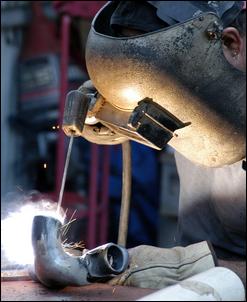
    An oxy acetylene torch was used to cut out the manifold plate. The cut was made on the outside of the line so that the resulting plate is a little larger than the gasket. The holes were cut on the inside of the marked line. A local welder did all the cutting and welding – his total time was 5 hours.
    Making Turbo Manifolds Part 1 & 2 2605_4lo

    The rough edge resulting from the oxy cutting was smoothed by an angle grinder. The port holes were not smoothed until the runners were welded in place, so that they could then be matched to the ports and the runner internal diameters in the one operation.
    Making Turbo Manifolds Part 1 & 2 2605_5lo

    The location of the turbo relative to the head was decided by simply holding the turbo in different positions and judging clearances. From this it could be seen that the manifold runners would probably need to head upwards a little before coming down towards the turbo inlet – that way, the turbo could be kept close to the block without the runners having to bend too sharply.
    Making Turbo Manifolds Part 1 & 2 2605_6lo

    The metal exhaust gasket was used whenever the spacing of the runners needed to be checked. Here the centre two runners can be seen taped together prior to welding. To allow them to nestle together, a section was cut from each 90-degree bend with a hacksaw.
    Making Turbo Manifolds Part 1 & 2 2605_7lo

    A small portion of the tape was cut away to allow a tack to be made. With the pipe bends then held together, the tape could be stripped off and more tacks – and then a proper weld – made.
    Making Turbo Manifolds Part 1 & 2 2605_8lo

    With the centre pipes shaped and then welded together, the outside cylinders could be organised. As can be seen here, again the head gasket is being used to determine pipe spacing. Ninety degree and a 45 degree bends are being used to form this runner, with a substantial amount of the 45-degree bend needing to be cut away. Again a hacksaw was used to do this.
    Making Turbo Manifolds Part 1 & 2 2605_9lo

    Here’s what the 45-degree bend looks like when shaped to match the other runner. An oval-shaped hole was cut on the side of the runner to suit the entering pipe.
    Making Turbo Manifolds Part 1 & 2 2605_10lo

    With both 45-degree bends cut to suit, and appropriate holes made in the existing runners, here’s what the assembly looked like. Note again how the exhaust manifold gasket is being used for sizing – if you buy a spare gasket and take careful under-bonnet clearance measurements, you can build the manifold without having your car off the road.
    Making Turbo Manifolds Part 1 & 2 2605_11lo

    The 45-degree bends were tacked and then welded in place before they were welded to the 90-degree bends. This was done for a very important reason – it allows...
    Making Turbo Manifolds Part 1 & 2 2605_12lo
    ....access for an oxy cutting torch to clean-up the internal transition at the pipe junction. If the 90-degree bend had been welded to the 45-degree bend first, the welding torch would not have been able to gain access to the junction.
    Making Turbo Manifolds Part 1 & 2 2605_13lo

    The rest of the runners could then be welded in place, and then welded to the manifold plate. This done, the previously cut out turbo mounting plate could be welded to the collector tube.
    Making Turbo Manifolds Part 1 & 2 2605_14lo

    The welds were cleaned-up with an angle grinder spinning a multi-flap sanding disc, and a high speed electric tool using a cutting burr. A round hand file was also used.
    Making Turbo Manifolds Part 1 & 2 2605_15lo

    The manifold could then be checked for turbo location.
    Making Turbo Manifolds Part 1 & 2 2605_16lo

    The next step was to have the manifold sandblasted, inside and out. Externally, this removes surface scratches and sanding marks and gives a uniform finish. Internally, it helps to remove any welding dags and scale. If you chose to have the manifold internally sandblasted, you should then clean the insides very thoroughly to get rid of any blasting sand that might remain.
    Making Turbo Manifolds Part 1 & 2 2605_17lo

    The manifold and turbo mounting flanges were then faced – that is, were machined flat so that good seals with the head and turbo could be gained. A local machine shop did this work. If you have this work done by a machine shop, it’s also a good time to have the manifold drilled and tapped to take a pressure tapping point and thermocouples (either one per cylinder or one just prior to the turbo).
    Making Turbo Manifolds Part 1 & 2 2605_18lo

    Cost

    The total cost of making the manifold was about AUD$500. This can be broken down to:

    Steel plate (0.5 metres x 12mm x 100mm) - $16

    Buttweld fittings (5 x 45-degree, 4 x 90 degree) - $72

    Welding and cutting (6 hours at AUD$50 per hour) – $300

    Sandblasting - $20

    Facing of both mounting plates - $90


    Turbo Manifold Design

    Start talking about turbo exhaust manifold design and people have all sorts of theories. Most say that equal-length, long runners should be used – irrespective of the length of runner that then results. But others say runners should be grouped on the basis of firing order. Sounds easy – until you ask some questions. Like, grouped exactly how on the basis of firing order? Or, how important is it that the runners are of equal length? For example, is it more important that runner length be equal – or the runners are organised to provide the best flow? After all, the longer the runner, inside a typical engine bay the more bends it’s likely to have in it and the greater resistance it will pose to flow.

    Let’s take a look at what the experts actually have to say.


    Making Turbo Manifolds Part 1 & 2 2605_19lo
    The original bible of turbocharging is Turbochargers, by Hugh MacInnes (published by HP Books). Despite being first published in 1978 – and so containing almost nothing that relates to EFI engines – the core content of the book has stood up surprisingly well in the years since. MacInnes suggests that turbo exhaust manifolds should use small diameter runners with about the same internal area as the ports and that in turbo engines, the use of “smooth flowing exhaust headers with beautiful swerving bends.... is more aesthetic than power-increasing”. Except for V8 engines, he makes no comments at all about grouping the flow from cylinders in any particular manner.

    Making Turbo Manifolds Part 1 & 2 2605_21lo
    Another old book is Turbocharging and Supercharging, by Alan Allard (first published by Patrick Stephens in 1982). Allard says: “The main criteria when designing and fabricating an exhaust manifold are: firstly, to build in sufficient strength to take the weight of the turbocharger system and to remain rigid without distortion or fracture even when working up to 1000 degrees C; and secondly, to have sufficient wall thickness (3.0mm minimum is recommended) to withstand the corrosion effects of running up to high temperature over a long period.”

    Allard suggests the use of a log-type manifold pipe of not more than 2.5 times, and not less that double, the area of one exhaust port. The log is joined to the individual exhaust ports with stubs with the same inside diameter as the exhaust ports, each as short as possible and of equal length. The stubs can enter the log at right-angles or be angled towards the turbo.

    Making Turbo Manifolds Part 1 & 2 2605_24lo
    However, while not mentioned in the text, a diagram shows a 1-3-4-2 firing order four cylinder engine using a manifold where cylinders 1 and 2, and 3 and 4, are paired and fed to a split-pulse turbine. In addition, again while it is not discussed in the text, many turbo racing engines are shown where equal-length long runners join at a common collector just prior to the turbo.

    Making Turbo Manifolds Part 1 & 2 2605_25lo
    Automotive Supercharging and Turbocharging Systems was first published in 1992 by Motorbooks International. The author is John Humphries. Of my references, this book provides the most detailed treatment of turbo exhaust manifolds. However, rather than making things clearer, if anything it further muddies the waters! The book suggests that there are two fundamentally different approaches to turbo exhaust manifold design.

    The first is to use a manifold with sufficiently large internal volume that the exhaust output pulses of each cylinder are damped and a more or less constant pressure is available to the turbine. The internal volume of the manifold sufficient to obtain this pulse dampening can be 1.4 – 6 times the swept volume of the engine. That rules out pretty well all long runner exhaust manifolds, although a log-type one of the sort suggest by Allard may fit into the bottom end of this scale, and the current fashion in the US for mounting the turbo at the back of the car (in a car with a front engine!) would also conform to this approach.

    The second approach is a pulse system, where the exhaust pulses provide additional short-term energy to the turbine. In a pulse-type manifold, Humphries suggests that the pipe runners should have a “cross-sectional area....not significantly greater than the geometric valve area at full lift [and] these connections should be kept short and free of sharp bends”.

    He says the reflection of pulses within the system will be determined by pipe length, exhaust temperature and the status (ie open, closed or partially open) of the exhaust valves. In addition, at pipe junctions the exhaust pulses will split, with smaller magnitude exhaust pulses travelling down each pipe. “The overall pressure wave system that occurs in such a manifold will be very complex, with pulses propagating from each cylinder, pulse division at each junction, total or partial reflection at an exhaust valve...and reflection from the turbine.”

    In order to take advantage of this pulse flow, “narrow pipes from several cylinders can be connected through a single branched manifold to one turbine....a four stroke engine which can have its cylinders grouped into threes is particularly attractive.” This is because “the opening periods of the exhaust valves follow successively every 240 degrees with very little overlap between them.... thus a sequence of pressure pulses arrives at the turbine...”

    Making Turbo Manifolds Part 1 & 2 2605_20lo
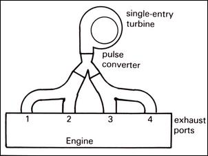
    Humphries suggests that the use of twin turbos on a six cylinder engine allows for efficient pulse operation, and where cylinder multiples are not in threes, a single turbo entry can be linked to multiple cylinders through “pulse converters”. Pulse converters are suitably shaped junctions which prevent reverse pulse flow. Humphries shows a four cylinder exhaust manifold with cylinders 1 and 2, and cylinders 3 and 4, paired and then coming together through a pulse converter junction.

    Making Turbo Manifolds Part 1 & 2 2605_22lo
    One of the more recent books on turbocharging is Corky Bell’s Maximum Boost (published by Robert Bentley, 1997). Bell suggest that it is important the manifold retains heat, prevents reverse flow (eg by the use of so-called reversion cones in the first section of each runner), and is designed to minimise thermal loads on each section of the manifold. The latter can be achieved by the use of runners from each cylinder travelling separately to the turbo inlet – that way, each runner is subjected only to the heating loads of one cylinder. It is implied but not stated that controlling these heating loads is more important than flowing the individual pulses in a sequence to the turbine – in the diagram the pipes are of unequal lengths.

    Bell also says that the experience with turbo F1 cars suggests that “the best manifolding is multiple-tube, individual runner style”. As with the other authors, he recommends the use of relatively small diameter runners with large wall thicknesses. With regard to pulse tuning, he says “a design that allows exhaust gas pulses to arrive at the turbine at regularly spaced intervals is ideal but difficult to achieve”.

    So what does one make of all of that?

    Firstly, it’s clear that these authors agree that the use of heavy wall tube (“steam pipe”) bends are preferable to thin gauge materials. Secondly, the individual cylinder runners should be sized smaller rather than larger, being near to port size. It also appears that if it is possible within the confines of the engine bay, equal-length runners that join at the turbo are to be recommended. In six cylinder engines, the grouping of two pairs of three cylinders to feed either two turbos or a single split-pulse turbine housing is to be favoured.

    However, unequal length runners are extremely widely used (few if any factory turbo cars have equal length runners in their cast manifolds) and some aftermarket tubular manifolds use branchings of unequal length runners. (Most of the latter are dubbed ‘pulse converter’ manifolds but whether the internal junctions conform to pulse converter geometries is not known.) Not one of the best known references is particularly critical of exhaust manifold designs which on a naturally aspirated engine would be seen as fatally flawed.

      Current date/time is Fri Apr 19, 2024 9:23 am